The AGV automatic charging device includes a charging mechanism and a power receiving mechanism; the charging mechanism includes a charging housing, a charging connecting rod, a charging head, positive and negative conductive plates; the power receiving mechanism includes a power receiving housing, a bending piece, and a power receiving plate And the ball plunger; the lower part of the power receiving housing is provided with a power receiving slot; the bending piece and the power receiving board are provided at the bottom of the power receiving slot; the inner bottom of the charging housing is provided with a first limit wall and The second limit stop wall; the charging connecting rod is located between the first limit stop wall and the second limit stop wall; a first spring is sleeved on the rod body; the tail of the charging head passes between the first limit stop wall The second spring is connected; the power receiving slot is provided with a power receiving port on one side in the horizontal direction and is bent upward at one side of the power receiving port; positive and negative conductive columns are provided on the power receiving board. The structure design is reasonable and compact, the charging mechanism and the power receiving mechanism are easy to plug, the docking is easy, and the use is safe and reliable.
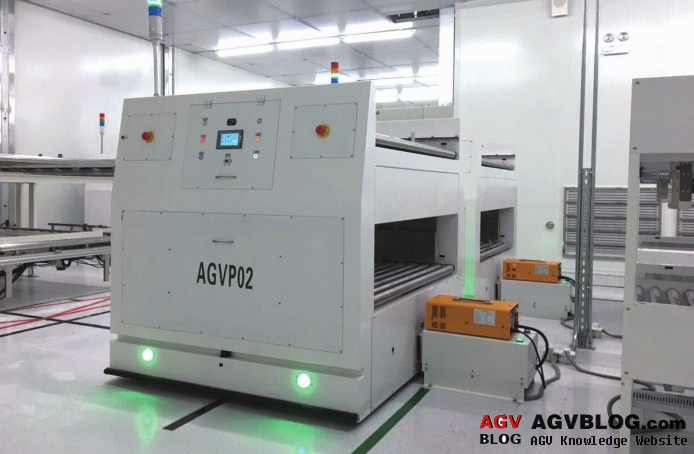
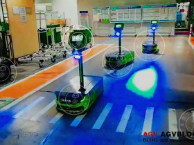
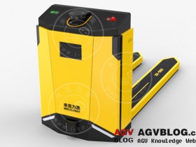
Introduction of AGV's automatic charging
The automatic charging device of AGV is characterized in that the power receiving mechanism further includes a ball plunger installed on the bottom of the slot of the power receiving slot; the inner bottom of the charging housing is provided with a first limit stop wall and a second limit position Retaining wall; the first limit retaining wall and the second limit retaining wall are parallel to each other; one end of the charging connecting rod is horizontally fixed to the second limit retaining wall, and the other end horizontally passes through the first limit retaining wall and the outlet end is connected to the charging The tail of the head is connected; the charging connecting rod is located on the rod body between the first limit wall and the second limit wall, and a first spring is sleeved; the head of the charging head is connected to the power receiving mechanism, and the tail of the charging head is The first limit stop wall is connected by a second spring; the power receiving slot is provided with a power receiving port for insertion of the charging head in the horizontal direction; the bending piece is matched and fixed on the side of the power receiving slot away from the power receiving port The bottom of the slot; the ball plunger is installed on the bottom of the slot on the side of the power receiving slot close to the power receiving port; the power receiving plate is fixed on the bottom of the slot on the side of the power receiving slot close to the power receiving port, and the bottom and the ball head post Plug contact connection, the power receiving board is located on one side of the power receiving port and is also bent upward; the power receiving board is provided with a positive pole and a negative pole The conductive column, when the charging head is matched and inserted into the power receiving slot, the positive electrode conductive column and the negative electrode conductive column respectively correspond to the mating contact connection of the positive electrode conductive sheet and the negative electrode conductive sheet.