1 Introduction
Automated Guided Vehicle ( AGV -Automated Guided Vehicle) is an important equipment in modern manufacturing enterprises and logistics systems. It is a self-driving automatic with a micro-control processor as the core, battery as the power, and non-contact guidance device. Guided delivery vehicle. It can automatically drive along the prescribed driving route and parking position according to the command issued by the monitoring system, according to the pre-designed program, according to the position information determined by the on-board sensors. AGV has the advantages of high transportation efficiency, energy saving, reliable operation, pollution-free, flexible transportation, etc., and has been widely used in many fields. From the expansion of supermarkets and workshops to large automated warehouses, hospitals and distribution centers, AGV has become one of the main symbols of industrial automation. This paper uses a reduced-scale model car to simulate the AGV on the actual production line , and uses infrared sensor technology to guide the AGV to move.

Load transfer AGV
2 hardware system design
2.1 Overall design
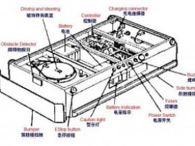
The automatic guided vehicle includes four parts: car body, controller, sensor and power device. Among them, the car body is simulated with a reduced-scale 200 mm × 300 mm rear-wheel-drive model car with a differential. The controller is based on the single-chip MC9S12DG128, and cooperates with the sensors and power devices on the car body to control the stable operation of the AGV . The sensor consists of an infrared sensor for direction finding and a Hall sensor for speed measurement. The power unit is composed of a DC motor driven by a battery and a steering gear, and controls the speed and steering respectively. These 4 parts are allocated with corresponding drive circuits, which can autonomously identify the path and control the model car to run stably. The AGV model car is shown in Figure 1.
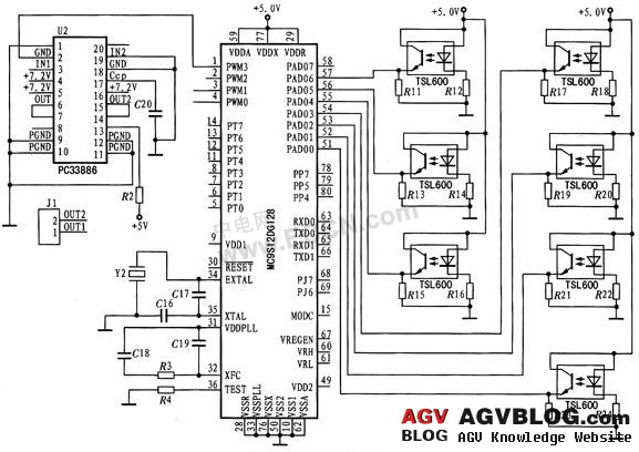
AGV and MCU can be regarded as an automatic control system, which is composed of 4 parts: sensors, information processing, control algorithms and actuators. The hardware part is based on the single chip microcomputer, equipped with sensors, actuators and corresponding drive circuits to form a control system; information processing and control algorithms are completed by control software. Figure 2 shows the block diagram of the hardware system circuit.
2.2 MCU introduction
AGV uses MC9S12DGl28 as the system controller. The device has 128 KB Flash, 8 KB RAM, 2 KB EEPROM, 8 input capture and output comparison channels, 2 8-bit or 16-bit pulse accumulators, and 8-channel PWM Wave generation channel, 8-channel 10-bit ADC channel or 16-channel 8-bit ADC channel, 2 SCI, SPI communication interfaces, 80-112 programmable I / O ports.
2.3 Power module
The power of AGV model car is provided by 7.2 V, 2 A / h battery. Since the working voltage and current required by different modules in the circuit are different, multiple voltage stabilizing circuits are needed to convert the battery voltage to the voltage required by each module. The LM7805 is a series regulator with an output voltage of 5 V. It mainly provides power for the microcontroller, infrared sensor, speed sensor and some interface circuits. The output of LM1117-ADJ is 2.85 V ~ 6 V adjustable regulated power supply. Adjust the voltage to 6 V through the potentiometer to power the servo. The battery 7.2 V power supply directly supplies power to the rear wheel motor of the ACV model car.
2.4 Speed detection module
The speed sensor uses the CS3020 Hall element. The Hall element is easy to use, and only needs a pull-up resistor to connect the output to the power supply to work normally. Stick 4 magnets on the inner side of the tire, and fix the Hall element in the right direction of the magnets. When the tire rotates once, the Hall element outputs 4 signals, and the tire circumference is 17 cm, so the time difference between each two signals is T, and the AGV travels 4.25 cm. By measuring T, calculate the AGV speed V = 4.5 cm / T.
2.5 Infrared detection module
The guidance methods of AGV model car are ultrasonic guidance, electromagnetic induction guidance, image recognition guidance, inertial navigation, infrared sensor guidance and so on. Due to the advantages of convenient use, low price, accurate guidance, and fast response speed of infrared sensors, this system is designed to use infrared sensor technology to guide AGV model cars. Selecting an infrared sensor with high transmission power and high receiving sensitivity is the basis for ensuring the reliable operation of the infrared detection circuit. The infrared sensor designed by this system uses reflective photocell TSL600. As shown in Figure 3, on the right is the infrared light-emitting diode and infrared receiving transistor, where VCC is +5 V, and R1 = 510 Ω and R2 = 20 kΩ are current limiting resistors, and OUT is the output signal. The amount of infrared light emitted by the infrared light-emitting diode reflects to the receiving transistor according to the depth of the color of the reflective medium. The receiving transistor is a photosensitive transistor. The more light received, the greater the output current. In this design, 7 pairs of infrared sensors are installed laterally at 10 cm in front of the AGV model car, 1 pair is installed in the direction of the AGV's central axis, and 3 pairs are installed on each of the left and right sides of the central axis. According to the signals output by the 7 pairs of sensors, the positional relationship between the black guide line and the AGV model car is determined, and reliable data is provided for the steering. The infrared receiver tube receives the infrared light reflected by the road to produce a varying voltage, reflecting the position of the track centerline. The output of the infrared sensor is analog, and the analog is converted to digital through the ADC of the MCU, which not only simplifies the external circuit design, but also retains the continuously changing voltage information of the infrared receiver tube, and obtains more accurate position information and eliminates ambient light through software algorithms. Impact. MC9S12DG128 has 8-channel 10-bit ADC or 16-channel 8-bit ADC. Considering that 8-bit effective value has met the system accuracy requirements, this system design uses 7 channels in 16-channel 8-bit ADC.
2.6 Drive control module
The motor starts using PC33886 as the driver, and the driving circuit principle is shown in the left part of Figure 3. The PWM3 generated by the MCU is input through the IN1 pin to adjust the output voltage of the OUT1 port of the PC33886, and IN2 is grounded to make the OUT2 output 0, so that a voltage difference is generated between OUT1 and OUT2, and the MCU is adjusted by changing the duty cycle of PWM3 Motor speed.
3 System software design
3.1 Control algorithm
In the continuous control system, the PID control algorithm that controls the deviation ratio (P), integral (I), and derivative (D) has been widely used. This digital PID control algorithm has a simple structure, easy to adjust parameters, and strong adaptability. The design of this system adopts incremental digital PID control algorithm, and adjusts the speed of DC motor through PWM.
3.2 program flow
The main program flow chart of the system is shown in Figure 4. The system first initializes the device, and then enters the parameter modification program. After the parameter setting is completed, the interrupt is turned on, and finally the position and speed control program is executed cyclically.
4 Conclusion
The experiment was carried out in a U-shaped driving road with an area of 5 000 min × 6 000 mm, and a black guide line with a width of 20 mm was drawn in the center of the road. Under normal circumstances, the upper limit of the speed of the given AGV model car is 1 m / s. The AGV runs smoothly on the guide line. It takes 22 s from the starting point to the end point and stops. The AGV model car speed is given. When the upper limit is 1.5 m / s, the AGV runs relatively smoothly on the guide line, and the whole journey takes 16 s. When the upper limit of the AGV model car speed is 2 m / s, the AGV driving is unstable, and sometimes it will rush It takes 12 s to get out of the guide line. According to the above experiment, the average speed of AGV stable operation is 1 m / s. AGV is not a racing vehicle. Generally, stability and safety are the main considerations on the industrial site. Therefore, the model car designed in this way fully complies with the AGV car's specifications in terms of stability , achieving independent guidance, high transportation efficiency, energy saving, reliable operation, and no pollution. And other requirements.